
Plugging an image texture into a material shader seems intuitive, but connecting a normal map in Blender without the correct intermediary node network is one of the quickest ways to ruin a clean render. You spend hours baking or generating intricate surface relief, drag the purple bitmap into the Shader Editor, hook it directly into the Normal input of your Principled BSDF, and immediately watch your geometry turn into a blotchy, pitch-black disaster.
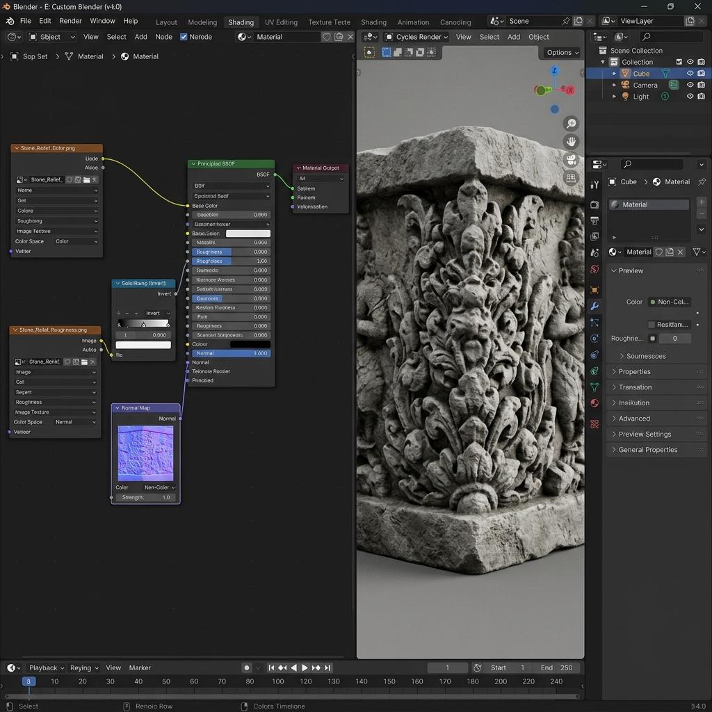
A proper Blender normal map node network routes a Non-Color Image Texture through a Tangent Space Normal Map vector node before entering the Principled BSDF.
Normal maps do not store RGB color values meant for human eyes; they store directional unit vectors encoded into the red, green, and blue color channels. If Blender treats those vectors like standard sRGB display pixels, the underlying math breaks, scattering surface reflections in random directions. Below is the definitive technical workflow to set up, calibrate, and troubleshoot normal maps in Blender 4.x across both Cycles and Eevee Next engines.
Why Connecting Normal Maps Directly to Shaders Fails
To understand why Blender requires a dedicated vector bridge, consider how light interaction is calculated on a polygon. A standard diffuse map instructs the renderer what hue to bounce back to the camera. In contrast, a normal map alters the perceived angle of the surface perpendicular relative to the incoming light rays.
Three critical configuration pitfalls frequently break normal map rendering in Blender:
- Color Space Mismatch (The sRGB Trap): By default, Blender interprets new image textures as
sRGB. This applies a non-linear gamma curve (~2.2) that warps vector calculations. Tangent vectors must be read in linear raw space (Non-Color). - Missing Vector Translation Node: An image texture outputs color values in a
0.0 to 1.0range. TheNormalsocket on the Principled BSDF expects a 3D vector in the range of-1.0 to +1.0. Without an intermediate Normal Map node, Blender cannot interpret coordinate transformations. - DirectX vs. OpenGL Handedness: Blender’s viewport and Cycles engine calculate tangent space using the OpenGL convention (Y-Axis points upward). If your texture was baked or generated for Unreal Engine or 3ds Max (DirectX convention, Y-Axis points downward), indented grooves will protrude outwards like swollen blisters.
[Blender Normal Map Shading Architecture]
[Image Texture Node]
  ├── Image: YourNormalMap.png
  ├── Color Space: Non-Color (MANDATORY)
  └── Color Output (Yellow Socket)
           │
           ▼
[Normal Map Vector Node]
  ├── Space: Tangent Space (Standard UV Mesh)
  ├── Strength: 0.5 to 1.5
  ├── UV Map: UVMap (Target Channel)
  └── Normal Output (Purple Socket)
           │
           ▼
[Principled BSDF Shader]
  └── Normal Input (Purple Socket) ──> [Material Output]
Step-by-Step Guide to Setting Up a Normal Map in Blender
Follow this three-step workflow inside the Shader Editor to ensure accurate tangent-space lighting calculation.
1. Configure the Image Texture Node Color Space
- Switch your top workspace layout to Shading to reveal the 3D Viewport and Shader Editor side-by-side.
- Press
Shift + Ain the Shader Editor, navigate to Texture > Image Texture, and place the node to the left of your Principled BSDF. - Click Open on the node and load your normal map image file (
.png,.exr, or.tiff). - In the Image Texture node properties, locate the Color Space dropdown menu (which defaults to
sRGB). - Change Color Space to Non-Color. (Skipping this step causes washed-out normal depth, excessive glossiness, and harsh dark banding across curvature boundaries).
2. Add and Wire the Normal Map Vector Node
- Press
Shift + Ainside the Shader Editor and navigate to Vector > Normal Map. - Place the Normal Map node between your Image Texture node and the Principled BSDF shader.
- Connect the yellow Color output socket of the Image Texture node into the yellow Color input socket of the Normal Map node.
- Connect the purple Normal output socket of the Normal Map node into the purple Normal input socket of the Principled BSDF shader.
- In the Normal Map node header, verify that the Space dropdown is set to Tangent Space (the default standard for deformable meshes and unwrapped props).
3. Inverting the Green Channel for DirectX Maps (If Necessary)
If your normal map was exported from a DirectX-centric baking tool or game asset pack, grooves like screw holes and stone cracks will illuminate from the opposite direction of your scene lamps.
- Press
Shift + Aand select Color > RGB Curves. - Drop the RGB Curves node directly onto the wire between the Image Texture and Normal Map nodes.
- In the RGB Curves node interface, click the G (Green) channel tab at the top.
- Drag the bottom-left point
(0.0, 0.0)straight up to(0.0, 1.0), and drag the top-right point(1.0, 1.0)straight down to(1.0, 0.0). This inverts the Y-axis without requiring external texture edits in Photoshop.
Diagnostic Reference Table for Blender Normal Map Errors
| Symptom (Visual Artifact) | Primary Cause | Immediate Solution |
|---|---|---|
| Material turns solid matte black or shows jagged faceted shading | Image Texture Color wired directly into Principled BSDF Normal socket | Insert a Vector > Normal Map node between the image and shader sockets |
| Relief looks washed out, weak, or overly shiny under grazing light | Color Space set to sRGB instead of raw linear data | Set the Image Texture node’s Color Space dropdown to Non-Color |
| Crevices pop outwards while ridges appear sunken inward | DirectX Y- channel used in Blender’s OpenGL Y+ viewport pipeline | Insert an RGB Curves node on the green channel and invert the curve slope |
| Dark black seams appear along polygon UV border edges | Mesh normals corrupted or split by improper smoothing angle | In Edit Mode press Shift + N (Recalculate Outside), then enable Auto Smooth |
| Normal detail shifts or stretches across animated skeletal meshes | Normal Map node set to Object Space instead of Tangent Space | Set the Normal Map node dropdown to Tangent Space |
Calibrating Normal Map Strength and Blending
Setting the Strength slider on the Normal Map node to excessive values (such as 3.0 or 5.0) often produces dark grazing-angle halos and breaks energy conservation in Cycles. For photorealistic surfaces, keep Strength between 0.6 and 1.2.
If you need to blend a high-frequency micro-detail normal map (such as leather pores or cloth weave) over a low-frequency macro normal map (such as deep folds or armor panels):
- Never use a standard Mix Color node in Multiply or Overlay mode; this corrupts the unit length of vector normals.
- Group your vectors using a custom Reoriented Normal Mapping (RNM) node cluster, or connect your macro detail to the Normal Map node and blend micro detail using a Bump node stacked into the Normal Map chain via its Normal input socket.
Creating Production-Ready Normal Maps for Blender
To bring architectural elements, sculpted reliefs, or props to life in Blender without spending hours sculpting billions of polygons, feeding your shader clean, studio-grade normal maps is essential. High-fidelity tangent-space maps allow low-poly game assets and real-time Eevee viewports to capture dynamic light and shadow with zero performance hit.
If you need to rapidly convert concept artwork, stone carvings, or photos into studio-grade normal maps with balanced tangent vectors, speed up your Blender texturing pipeline with our Free Online Normal Map and PBR Generator — Try Weathered Stone Relief. You can also generate perfectly tileable environmental surfaces for your architecture scenes using our Seamless Texture Generator Online.
Blender Normal Map Setup Quick Checklist
- Image Texture Color Space explicitly set to Non-Color.
- Intermediate Vector > Normal Map node wired between Image and Principled BSDF.
- Normal Map space set to Tangent Space for UV-unwrapped meshes.
- Green channel orientation checked (Inverted via RGB Curves if source map is DirectX).
- Mesh geometry normals recalculated (
Shift + N) to prevent black polygonal seams.
Related reading: What is a Normal Map? · How to Use Normal Maps in Unity and UE5 · Fix Blender Textures Turn Black After Baking · Image to Normal Map Converter